Product line 10 / 12 · CompactPCI Chassis
A strong card is nothing without a strong cage: CompactPCI system chassis built around your backplane, board depth and airflow.

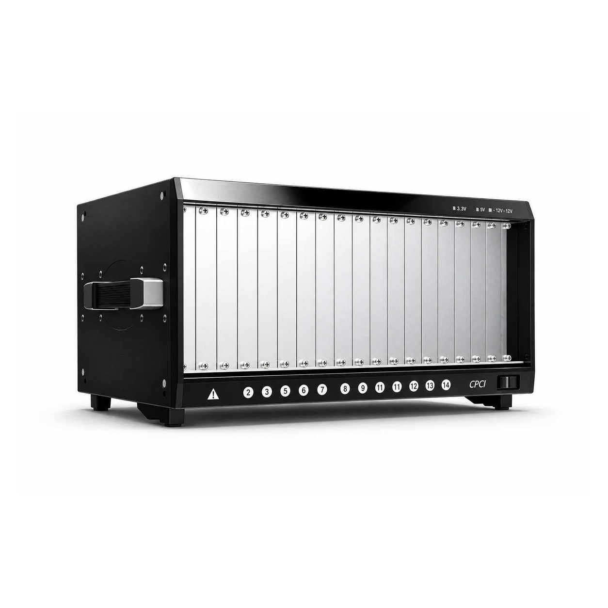
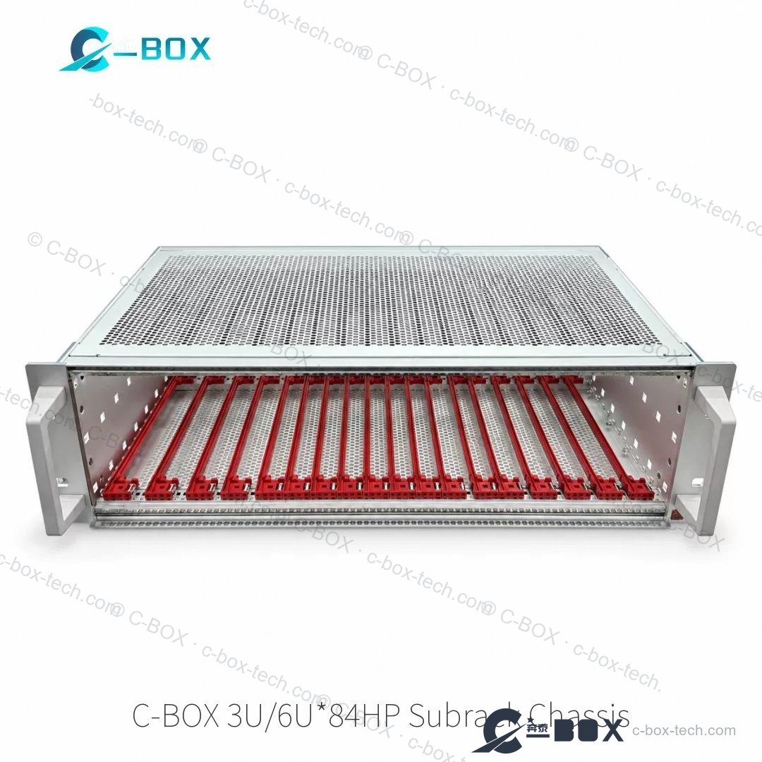
C-BOX CompactPCI chassis are sheet-metal systems engineered around a specific backplane. Our reference platform follows IEC 60297-3-101 / -102 / -103 and IEEE 1101.1 / .10 / .11: front plug-in units 3U × 160 mm deep, rear-I/O boards 3U × 80 mm, CompactPCI and CompactPCI PlusIO backplanes to PICMG 2.0 R3.0 and PICMG 2.30 R1.0, 32-bit PCI and PCIe Gen2 signalling. Cooling is a 1U hot-swap fan unit with bottom-to-top airflow; power comes from a 19″ pluggable PSU (250 W, 3U / 8HP typ.) and a dedicated HDD bay can be fitted. Slot count, depths, guide-rail set and panel machining are all specified per project — the chassis arrives ready for your boards, no rework, no adapters.
| Format | 3U / 6U CompactPCI · PlusIO, 19″ |
| Standards | IEC 60297-3-101/-102/-103 · IEEE 1101.1/.10/.11 |
| Backplane | PICMG 2.0 R3.0 · PICMG 2.30 R1.0, 32-bit PCI / PCIe Gen2 |
| Board depth | front 3U × 160 mm · rear I/O 3U × 80 mm (typical) |
| Cooling | 1U hot-swap fan unit, bottom-to-top airflow |
| Power | pluggable 19″ PSU 250 W (3U / 8HP typ.) |
| Options | HDD bay · EMC guide rails with coding · custom panels |
Product videos
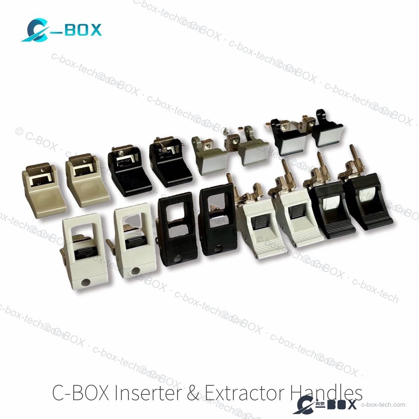
A guided tour of our CompactPCI platform — shielded plug-in panels, inserter/extractor handles, EMC guide rails with ESD, backplane and power options from 150 W to 1 kW — followed by a 20-second assembly clip from our workshop.
CompactPCI chassis walkthrough with English interpretation (5 min)
CompactPCI chassis assembly in 20 seconds — C-BOX workshop
Same interface dimensions as the nVent SCHROFF equivalents — our own tooling, material and finish.
Every model has its own page with specifications and RFQ. Use your browser search (Ctrl/Cmd+F) on this page, or send us the number and we will quote it.
Self-developed CompactPCI system chassis. Every model has its own page with specifications and RFQ.
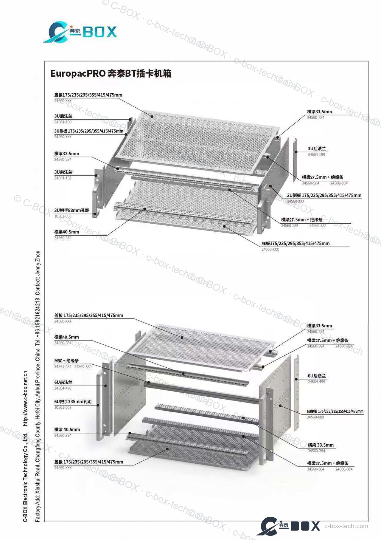
Modular 19″-style BT card chassis — 3U and 6U kits with every part numbered, from cover and side panels to flanges, EMC rails and insulating strips.
Buyer guide
The bus you are committed to is already decided by your boards. What differs at chassis level is pitch, cooling and mechanical ruggedness.
All three sit in a 19 inch subrack frame and share the same Eurocard heritage, so they look alike from the front. The differences that matter to a chassis specification are board pitch, cooling and the target environment.
| CompactPCI | PXIe | VPX | |
|---|---|---|---|
| Board pitch | 0.8″ / 20.32 mm | 0.8″ / 20.32 mm | 1.0″ / 25.4 mm |
| Typical height | 3U / 6U | 3U / 6U | 3U / 6U |
| Cooling | Forced air | Forced air, instrument-grade | Forced air or conduction-cooled |
| Strength | Rugged, industrial, telecom | Timing/sync, measurement | High bandwidth, harsh environments |
| Best for | Industrial control, telecom, rail | Test & measurement, ATE | Defence, aerospace, rugged embedded |
In practice: stay with CompactPCI when the ecosystem and cost matter and the environment is industrial; choose PXIe when you need multi-module synchronisation and instrument-grade cooling; choose VPX when board power, bandwidth or shock/vibration exceed what air cooling can serve, and specify conduction-cooled rails and wedgelocks accordingly.
A CompactPCI chassis is chosen by the card set, not by the enclosure. Slot count, backplane topology and whether rear transition modules are used fix the mechanics before the chassis is picked.
CompactPCI uses the 2 mm hard-metric connector in a 3 U or 6 U Eurocard format, so a chassis is a 19″ subrack with a backplane, a card guide set, cooling and power. The three numbers that decide the model are: how many slots the backplane has, whether it is a single segment or bridged, and how deep the cards are.
| Decision | Options | Mechanical consequence |
|---|---|---|
| Slot count | 8, 14, 21 slot (3 U); two-tier 6 U | sets chassis width in HP and the number of guide rails |
| Backplane | 32-bit / 64-bit, single or multi-segment | segment bridges change which slots can hold a system card |
| Rear I/O | rear transition modules or rear cabling | RTMs need a deeper chassis and a rear panel opening per slot |
| Cooling | front-to-rear fans, bottom-to-top | front-to-rear needs a sealed card area to be effective |
| Power | internal AC PSU, DC input, dual feed | dual feed doubles the input assembly and the PDU wiring |
3 U gives one row of cards and 100 mm of board height; 6 U gives two tiers of 3 U or one 6 U card, doubling front-panel area and connector space. Most telecom and industrial systems stay at 3 U; instrumentation and imaging systems move to 6 U when the front panel runs out of room for connectors.
Where this product line is typically used.
A 3U CompactPCI chassis takes 100 × 160 mm front boards with an optional 80 mm rear-I/O board behind the backplane, so the same 3U mechanics cover a benchtop unit and a full rack system — only the slot count and the cooling change. A typical desktop build is 4 U outside, 44 HP wide and 8 slots deep, like the 4U / 8-slot CPCI PlusIO desktop system (24579-605); a 19-inch rack version goes up to 21 slots with the 1U hot-swap fan unit underneath. Board depth decides the rail: 160 mm cPCI/VME64x guide rails for standard boards, 220 or 280 mm versions when the payload is deeper.
A 6U cPCI chassis gives 267 mm of panel height instead of 133 mm: either one 6U board per slot, or two 3U tiers split by a centre rail, which is how most telecom and test systems mix a 3U front card with a 3U rear transition module. The trade-offs are airflow and access — a 6U cage needs a taller fan tray and the guide rails must carry the extra board mass, so we confirm rail grade and fan sizing against the slot count rather than quoting from the height alone. Backplanes follow PICMG 2.0 R3.0 or the 2.30 PlusIO profile; if you are still deciding between the two, the note below on CompactPCI versus PlusIO covers what changes at the connector.
CompactPCI shares its 3 U Eurocard mechanics with three other lines we build, so a cPCI project often turns into one RFQ for the whole rack: IEC 60297 84 HP subracks when you want the cage without a backplane, PXI Express chassis when the instrument modules are PXIe but the mechanics stay the same, and rugged 3U OpenVPX chassis when the payload moves to a VITA 46 fabric. Guide rails, coded front panels and handles are interchangeable across all four.
Parts that usually go together with CompactPCI Chassis.
CAD & 3D
Free production geometry for these chassis and subracks — drop straight into your assembly.
Related categories
As a working system: CompactPCI or CompactPCI PlusIO backplane (PICMG 2.0 R3.0 / PICMG 2.30 R1.0), 19" pluggable PSU (250 W, 3U / 8 HP typical) and a 1U hot-swap fan unit with bottom-to-top airflow. An HDD bay can be fitted. Slot count, depths, guide-rail set and panel machining are specified per project.
PlusIO adds hybrid slots with rear I/O and PCIe Gen2 signalling alongside 32-bit PCI. Choose it when the rear connector area has to carry signals. Front cards are 3U x 160 mm and rear I/O boards 3U x 80 mm, to IEC 60297-3-101/-102/-103 and IEEE 1101.1/.10/.11.
One slot is 4 HP at 20.32 mm pitch, so 8 slots need 32 HP, 14 slots 56 HP and 21 slots the full 84 HP. A 21-slot 3U backplane fills the frame completely, leaving no side space for cable management inside the rack, while a 14-slot build keeps 28 HP that is usually taken by a cable entry and the PSU.
A single-segment backplane puts every slot on one bus. A bridged or multi-segment backplane limits which slots can hold the system card and where a bridge card sits, and some segments are consumed by rear I/O — a 5–8 slot segment may offer no rear-plane routing at all. Mark the system slot and the bridge positions on the board list before the chassis is specified.
Rear transition modules need a rear panel opening per slot and a deeper chassis: a 6U two-tier build with RTMs typically wants 1000 mm of usable cabinet depth. If rear signals leave by cable instead, the frame stays shallower but the rear needs a cable entry and strain relief. Decide early — this changes the frame depth, not just the rear panel.
Move to 6U when the front panel runs out of room for connectors, not when you need more slots. A 6U card gives 233.35 mm of board height and 261.8 mm of front panel, so I/O density roughly doubles per slot, and a two-tier 3U build doubles the board count. The price is a centre rail, a second rail row, a stronger airflow path and more cabinet depth.
Made in our own plants — chassis and precision parts from Kunshan, cabinets and surface finishing from Hefei: CNC punching, press braking, CNC machining, assembly, inspection and export packing in-house.
Kunshan plant →Hefei plant →Cross-referencing against major international 19″ system part numbers is our daily routine — we quote within 24 hours for standard items.