Product line 06 / 12 · Subracks & 19″ Chassis
Our highest-volume line: modular 19″ subracks and card chassis for CompactPCI, PXIe, VPX and custom backplane systems.
Replacement frames for discontinued systems — 6U / 19″ frames for FH98-type dispatch and legacy transmission equipment, six depths 175–475 mm, built to the existing hole pattern. See the replacement-frame page →
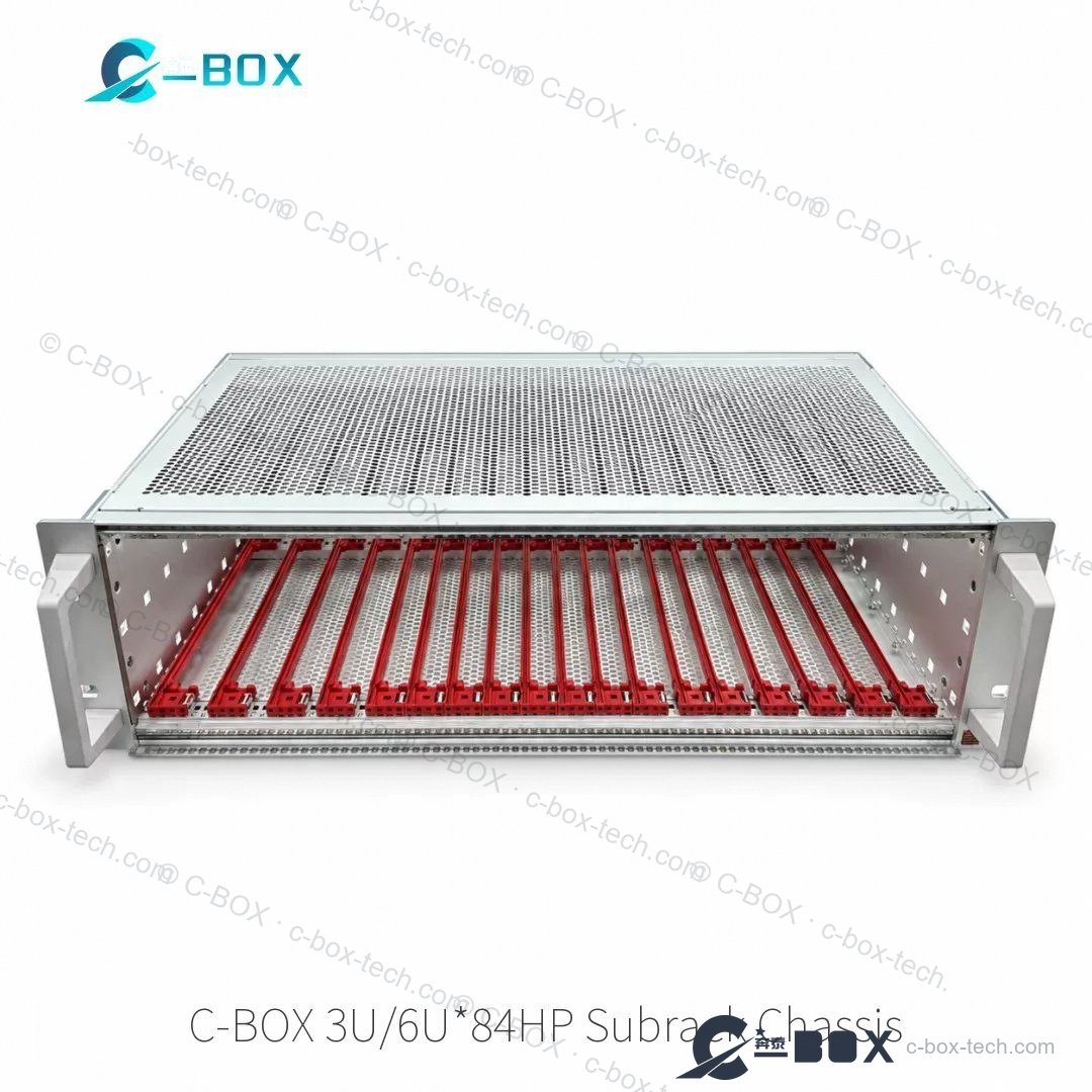
Watch a CPCI subrack being built at our bench — shielding strips, ESD card guides, backplane and plug-in modules fitted, then the completed unit stands up for inspection. Standard sizes 3+1U and 6+1U (custom 4+1U), depths 160 mm front / 80 mm rear or 220 mm front / 80 mm rear.
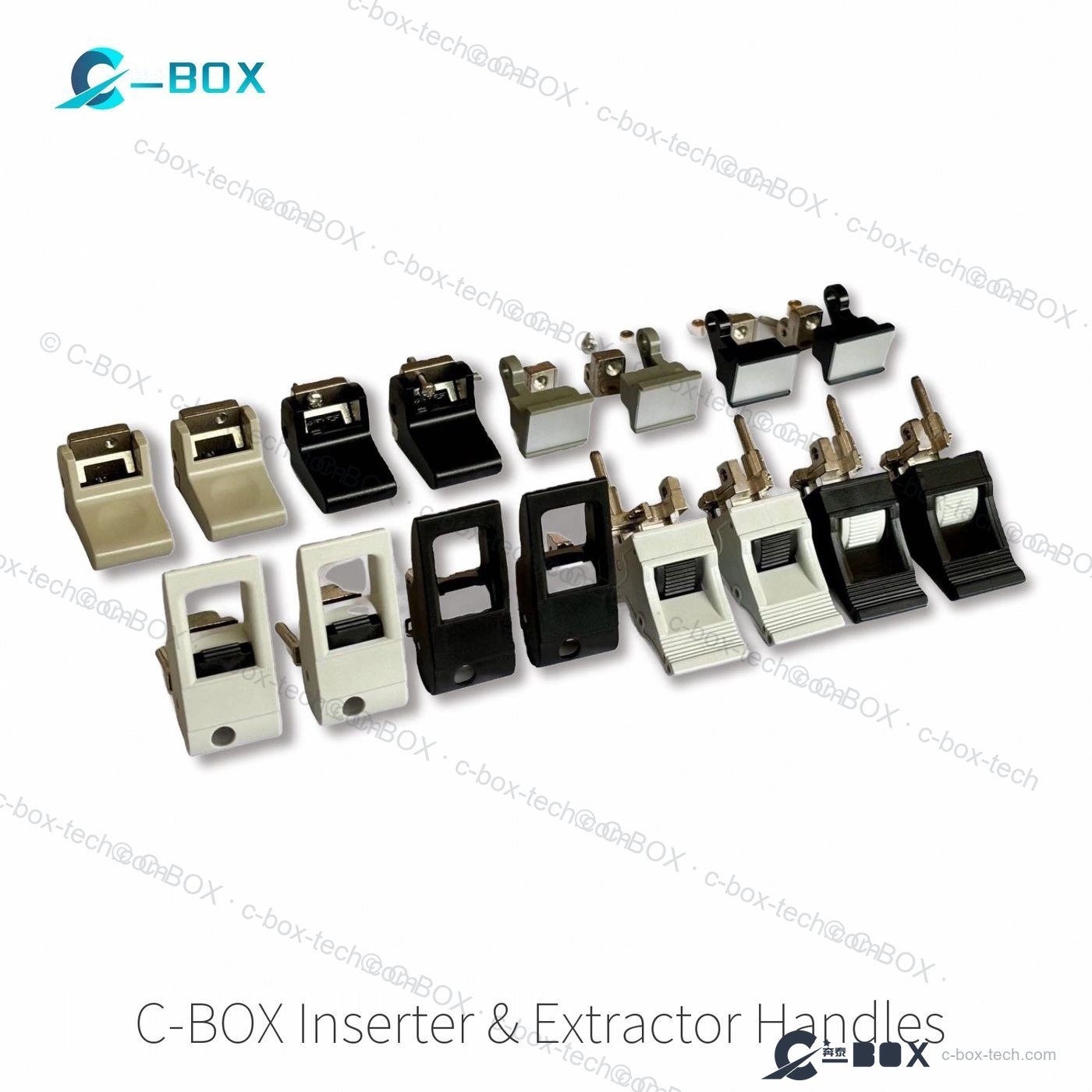
C-BOX subracks are the backbone of most systems we ship. One modular platform covers every configuration: 19″ side panels and horizontal rails dimensioned to IEC 60297-3-103 and IEEE 1101.10/11, supplied as space-saving kits or individually configured. Choose aluminium or AlZn-coated steel construction, light or flexible kit styles, backplane or connector mounting. EMC shielding is easily retrofitted, and CompactPCI / VME64x insertion and extractor handles are supported natively. For harsh duty the rugged variants add shock and vibration resistance up to 25 g — tested to MIL-STD 167, IEC 61587 DL 3 and MIL-STD 810 — alongside wall-mounting kits and DIN-rail kits for DIN 43880 supply modules.
| Heights | 1U / 2U / 3U / 4U / 6U / 9U |
| Width | 84HP (19″ mounting) |
| Depths | 100 – 500 mm, stepless on request |
| Standards | IEC 60297-3-103 · IEEE 1101.10 / 11 |
| Material | aluminium or AlZn-coated steel |
| Installed load | 7.5 kg (light kit) / 11 kg (flexible kit), version-dependent |
| Shock / vibration | 5 g standard · up to 25 g rugged (MIL-STD 167, IEC 61587 DL 3, MIL-STD 810) |
| Delivery | assembled or space-saving flat-pack kit |
Same interface dimensions as the nVent SCHROFF equivalents — our own tooling, material and finish.
Every model has its own page with specifications and RFQ. Use your browser search (Ctrl/Cmd+F) on this page, or send us the number and we will quote it.
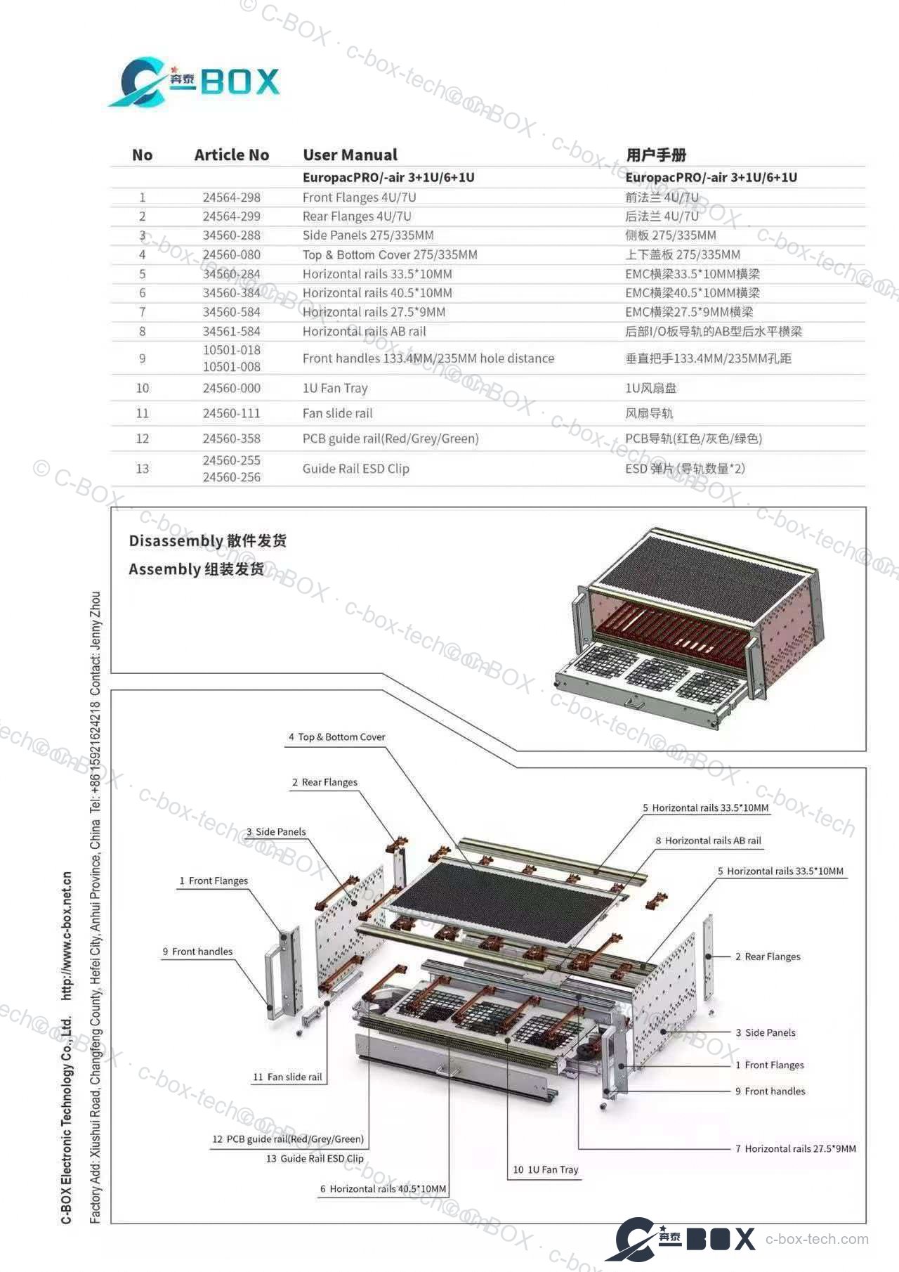
Every part in the kit is numbered — front and rear flanges, side panels, top & bottom covers 275 / 335 mm, EMC horizontal rails 33.5 × 10 mm and 27.5 × 9 mm, AB rail, front handles 133.4 / 235 mm hole distance, 1U fan tray, PCB guide rails and ESD clips.
Buyer guide
Terminology, height and width are where most subrack specifications succeed or fail. These two notes cover the decisions engineers ask us about most.
A 19 inch subrack, a card cage and a system chassis are the same family described from three angles. The words are used loosely, but they describe different levels of completeness. Specifying the wrong one is the usual cause of a quote that comes back with the wrong content.
| Term | What it is | You still need to add |
|---|---|---|
| Card cage | Bare mechanical frame: side panels, horizontal rails, guide rails | Backplane, cooling, front panels |
| Subrack | Card cage plus rails, coding, EMC gaskets and mounting hardware | Backplane, power, cooling |
| Chassis | Complete assembly: subrack, backplane, power supply, cooling, front panels | Plug-in boards only |
Specify a card cage when you already own the backplane and cooling; a subrack when you want the mechanical platform but will fit your own electronics; a chassis when you want a system-level build around a defined bus. In every case state the bus standard, height in U, width in HP, board depth, and the required EMC/ESD level.
Height follows from board size and front-panel real estate, not the other way round.
| Height | Panel height | When to choose it |
|---|---|---|
| 3U | 133 mm | Single Eurocard height; CompactPCI / PXIe / VPX single-slot boards, dense I/O. |
| 6U | 267 mm | Two tiers of 3U, or 6U VME/VXS boards; more connector and label area. |
| 9U | 400 mm | Mixed 6U + 3U partitions, or tall custom I/O and cable entry zones. |
A 6U rack also lets you split the assembly area with a rear centre rail (for example 2 × 3U). Choose 3U for the widest board ecosystem and lowest cost; step up to 6U or 9U only when board size or front-panel density requires it.
Most subrack problems are not manufacturing defects. They are stack-up errors between three drawings made by three people — the subrack, the front panel, and the board with its connector and handle.
A 19″ subrack is defined by a small set of numbers: 482.6 mm overall width, 465.1 mm clear aperture between the mounting angles, 1 U = 44.45 mm, and 1 HP = 5.08 mm. Everything inside — rails, panels, plug-in units — is positioned from that grid. When a build does not go together, it is almost always because one drawing was made from an edge instead of the grid.
Three places account for nearly every interference case we see: a front panel specified to the subrack outer width instead of the HP grid; a plug-in unit drawing that measures from the panel face rather than the connector face; and a rear panel or backplane that assumes the rail sits flush with the mounting angle. Each is a 1-3 mm error that only appears at assembly.
Send the subrack part number, the plug-in unit drawing and the board outline together, and ask for one assembly review before the panels are machined. If the panels are already cut, send a photo of the first assembled bay with a rule across the panel gap: an even gap line across five or six units tells you the grid was respected, an uneven one tells you where the drawing drifted.
For builds that combine parts from more than one supplier, keep the tolerances in one document. Two sources that each hold ±0.2 mm against a different reference will not stack to the same result as one source holding ±0.2 mm against the grid.
Where this product line is typically used.
Product video
Watch the enclosure family being built — sheet-metal forming, finishing and assembly under one roof.
Enclosure production at C-BOX
Product demo
Our 3U shielding subracks carry a conductive surface treatment and EMC shielding strips along the guide rails, so every front panel bonds to the frame. The clip shows front plug-in units in 3U 4HP and 8HP, and the frame-type 3U 10HP plug-in unit, being inserted and removed — the same front-plug-in family used on the subracks above. EMC contact is verified by sampling tests on each production batch.
3U shielding subrack: inserting and removing front plug-in units (4HP / 8HP / frame-type 10HP)
Panel and plug-in widths follow the common 84 HP front-panel grid, so C-BOX panels and plug-in units fit comparable 19″ card cages. Schroff™ is a trademark of its respective owner; C-BOX is an independent manufacturer and is not affiliated with any subrack brand.
84 HP is the standard assembly width of the 19-inch mechanics family: 84 × 5.08 mm = 426.7 mm of usable width inside a 482.6 mm (19″) front panel. What fits therefore depends on module width, not on the subrack: 21 × 4 HP, 10 × 8 HP, 7 × 12 HP, or a mix of wider specials. Height and depth are quoted separately — 1U to 9U, 100 to 500 mm — and the rail pair has to match the board depth, not just the height. For 84 HP builds we usually ship heavy front horizontal rails with long lip (34560-384) and M3 threaded insert strips (34561-484); both are also the parts most often asked for as cross-supplier equivalents.
IEC 60297 fixes the dimensions; IEEE 1101.10 adds the features that make a rack serviceable. In practice that means EMC/ESD contact surfaces between rail and board, coding keys so a plug-in unit cannot be inserted in the wrong slot, a defined interface for injector/extractor handles, and reinforced rail geometry for boards that are inserted under load. IEEE 1101.11 covers the rear I/O and backplane area in the same way. If your drawing says “1101.10” and the quote came back as a plain 60297 subrack, that difference is usually what is missing — EMC guide rails, coded rails and ESD clips are the parts to add, and the 700 N inserter/extractor handles only work on the .10 interface.
A subrack is often the shell around a bus that someone else has already chosen. If the boards are VPX or OpenVPX, the same 84 HP width is used by our rugged 3U OpenVPX chassis family with heavy-duty EMC rails and forced-air cooling; if they are cPCI, the mechanics move to a PICMG 2.0 CompactPCI chassis with hot-swap fan tray; and for instrument racks the 8-slot and 18-slot PXI Express chassis share the same 3 U Eurocard tooling. Rails, cross members and panel cut-outs are common across the four lines, so one drawing review usually covers the whole rack.
Parts that usually go together with Subracks & 19″ Chassis.
CAD & 3D
Free production geometry for these chassis and subracks — drop straight into your assembly.
Related categories
Standard kits take 5 g shock and vibration. Rugged variants reach 25 g, tested to MIL-STD 167, IEC 61587 DL 3 and MIL-STD 810. Wall-mounting kits and DIN 43880 PSU kits use the same platform.
Aluminium where weight and thermal behaviour matter, AlZn-coated steel where strength and cost matter. Both are dimensioned to IEC 60297-3-103 and IEEE 1101.10/.11, in heights 1U-9U, width 84 HP, depths 100-500 mm, as kits or individually configured.
Yes - shielding is retrofit-ready, whether the subrack was supplied as a kit or configured. CompactPCI / VME64x insertion and extractor handles are supported natively, and backplane-ready card cages cover CompactPCI, PXIe and VPX.
Start from the backplane: a backplane-mounted frame carries the board connectors on a rear PCB, a connector-mounted frame uses DIN 41612 / IEC 60603-2 connectors in the rails. Then the load. 24564 light kits take 7.5 kg on 19″ brackets, 24563 F side panels take 11 kg with depth adjustable in 15 mm steps, and 24567 H panels are tox cold-welded for railway and heavy loads, up to the rugged 25 g version. Shielded variants add a stainless EMC gasket. Compare 24563-131, 24564-131 and 24567-461.
3U gives one tier of 100 mm boards. 6U gives 233.35 mm of board height, as one 6U card or two 3U tiers, and the front panel grows from 128.4 mm to 261.8 mm. A 6U frame also needs a centre rail and a second row of horizontal rails. Budget cabinet depth at the same time: most 6U two-tier builds with rear I/O land at 1000 mm of usable depth.
1 HP is 5.08 mm, so the standard 84 HP frame is 426.7 mm of internal width, and one slot at 20.32 mm pitch is 4 HP. That makes 21 slots the full 84 HP, 14 slots 56 HP and 8 slots 32 HP. Whatever is left over is what you have for side panels, cable entry and handles — a 21-slot build has no spare width at all, so fix the rear cable route before the slot count.
Depth is quoted as insertion depth D1: 175, 235, 295, 355, 415 or 475 mm. Board depth is D1 minus 15 mm because the rails sit on a 15 mm grid, so a 295 mm kit takes a 280 mm board. Rear I/O changes the sum: a 6U × 275 build carries 160 mm at the front and 80 mm at the rear, so state both figures whenever a rear transition module is in the plan.
IEEE 1101.10 adds EMC contact springs, coding keys, handle fixing holes and a defined shielding gasket. Whether a frame can take them depends on the side panel it was built with: the light L panel has no .10 configuration, while the F and H panels can be ordered with it. In practice you change the side panel rather than bolt parts on, so specify .10 at the start if a retrofit is possible later.
Made in our own plants — chassis and precision parts from Kunshan, cabinets and surface finishing from Hefei: CNC punching, press braking, CNC machining, assembly, inspection and export packing in-house.
Kunshan plant →Hefei plant →Cross-referencing against major international 19″ system part numbers is our daily routine — we quote within 24 hours for standard items.